SPI
SPI (Serial Peripheral Interface) is a programmable interface for transferring data quickly to peripherals that require high performance.
The SPI protocol is a serial communication method that controls the clock signal as master and other peripherals connected to SPI as slaves. This protocol is used by peripherals, such as heart-beat pulse sensors and graphic displays, that require fast data transfer.
Figure: SPI interface diagram
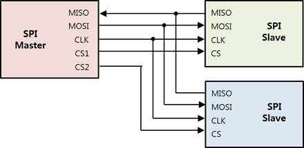
The SPI is a communication method between 1 master and multiple slave devices. In the above figure:
- CLK (SCLK or SCK) is a simple synchronization signal and a communication clock.
- The data flows from the master to the slave in the MOSI (Master Out Slave In) line, and from the slave to the master in the MISO (Master In Slave Out) line. Full duplex data communication is possible with 2 lines (MOSI and MISO).
- CS (Chip Select) is a signal for selecting a slave device.
SPI supports half duplex read/write and full duplex transfer.
To use SPI, you must set the following:
-
SPI mode
Figure: SPI modes
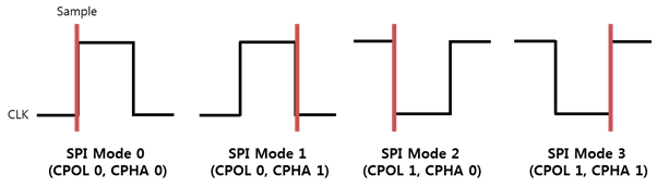
Each of the 4 available SPI modes defines a specific combination of clock polarity (CPOL) and clock phase (CPHA).
Table: SPI modes
SPI mode Polarity (CPOL) Phase (CPHA) Description SPI MODE 0 0 0 CLK (Clock) is first low and data is sampled on the rising edge of each clock pulse. SPI MODE 1 0 1 CLK is first low and data is sampled on the falling edge of each clock pulse. SPI MODE 2 1 0 CLK is first high and data is sampled on the falling edge of each clock pulse. SPI MODE 3 1 1 CLK is first high and data is sampled on the rising edge of each clock pulse. -
Bit order
The bit order refers to the sequential order in which bytes are arranged into larger numerical values. MSB indicates that the most significant bit is transmitted first. LSB indicates that the least significant bit is transmitted first.
-
Bit per word
The bit per word refers to the number of bits to be transmitted at a time when data is exchanged with a connected slave. Normally, it is set to 8 bits per word.
-
Frequency
The frequency refers to the clock signal in Hz. Since the frequencies are different for each slave device, the applicable value must be checked from the peripheral’s specification.
Opening and Closing a Handle
To open and close a handle:
-
To open a SPI handle, use the
peripheral_spi_open()function:int bus = 2; int chip_select = 0; peripheral_spi_h spi_h; peripheral_spi_open(bus, chip_select, &spi_h);The
busandchip_selectparameters required for this function must be set according to the following tables.Table: Raspberry Pi 3 and Raspberry Pi 4
Pin name Bus (parameter 1) Chip Select (parameter 2) SPI0_MOSI SPI0_MISO SPI0_CLK SPI0_CS0 0 0 SPI0_MOSI SPI0_MISO SPI0_CLK SPI0_CS1 0 1 Note
For more information on the pin names and locations, see Supported Protocols.
-
To close a SPI handle that is no longer used, use the
peripheral_spi_close()function:peripheral_spi_close(spi_h);
Setting the SPI Mode
To set the SPI mode, use the peripheral_spi_set_mode() function with 1 of the following mode types:
PERIPHERAL_SPI_MODE_0: CLK is active high and sampled at the rising edge.PERIPHERAL_SPI_MODE_1: CLK is active high and sampled at the falling edge.PERIPHERAL_SPI_MODE_2: CLK is active low and sampled at the rising edge.PERIPHERAL_SPI_MODE_3: CLK is active low and sampled at the falling edge.
peripheral_spi_set_mode(spi_h, PERIPHERAL_SPI_MODE_1);
Setting the Bit Order
To set the bit order, use the peripheral_spi_set_bit_order() function with 1 of the following bit order types:
PERIPHERAL_SPI_BIT_ORDER_MSB: Use the most significant bit first.PERIPHERAL_SPI_BIT_ORDER_LSB: Use the least significant bit first.
peripheral_spi_set_bit_order(spi_h, PERIPHERAL_SPI_BIT_ORDER_MSB);
Note
The Raspberry Pi 3 and Raspberry Pi 4 boards do not support the LSB bit order.
Setting the Bits per Word
To set the bits per word, use the peripheral_spi_set_bits_per_word() function:
uint8_t bits_per_word = 8;
peripheral_spi_set_bits_per_word(spi_h, bits_per_word);
Setting the Frequency
To set the frequency, use the peripheral_spi_set_frequency() function.
The frequency unit is Hz.
uint32_t frequency = 1024;
peripheral_spi_set_frequency(spi_h, frequency);
Reading, Writing, and Transferring Data
To read, write, and transfer data:
-
To read data from a slave device, use the
peripheral_spi_read()function:uint8_t data; uint32_t length = 1; peripheral_spi_read(spi_h, &data, length); -
To write data to a slave device, use the
peripheral_spi_write()function:uint8_t data = 0x80; uint32_t length = 1; peripheral_spi_read(spi_h, &data, length); -
To exchange bytes data with a slave device, use the
peripheral_spi_transfer()function:uint8_t tx_data[2] = {0x80, 0x01}; uint8_t rx_data[2]; uint32_t length = 2; peripheral_spi_transfer(spi_h, tx_data, rx_data, length);