
The Metal Detector sample application demonstrates how you can use the magnetic sensor. You can monitor the strength of the magnetic field and the direction where the presence of metal was recognized using the Gear device.
The following figure illustrates the main screen of the Metal Detector.
Figure: Metal Detector screen
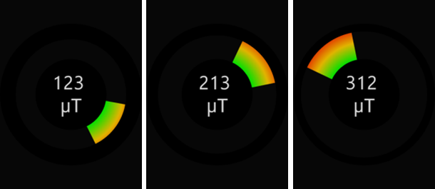
The application opens with the main screen that displays example values and directions of the measured magnetic field.
Prerequisites
For this sample application, you need a device with a magnetic sensor.
Source Files
You can create and view the sample application project including the source files in the IDE.
| File name | Description |
|---|---|
| config.xml | This file contains the application information for the platform to install and launch the application, including the view mode and the icon to be used in the device menu. |
| css/style.css | This file contains the CSS styling for the application UI. |
| images/ | This directory contains the images used to create the user interface. |
| index.html | This is a starting file from which the application starts loading. It contains the layout of the application screens. |
| js/app.js | This file contains the functions responsible for back key and low battery handling. |
| js/core/ | This directory contains the application framework. |
| js/helpers/calculations.js | This file contains the helper for necessary calculations. |
| js/models/magnetic.js | This file contains the module for managing the magnetic sensor. |
| js/views/main.js | This file contains the functions for implementing the application views and handling the application events. |
| lib/tau/ | This directory contains the external libraries (TAU library). |
Implementation
Application Layout
The Metal Detector sample application defines the main screen layout with the main working space and an error popup that can be displayed when the application has no access to the magnetic Sensor API:
- Main working space
The main working space contains 3 elements. To be positioned centrally to the UI, each of them is wrapped by a div element with the frame class:
- The div element with the pointer ID is responsible for showing the direction from which the presence of metal was recognized. This element can be rotated. The rotation angle depends on the current values of the magnetic sensor.
- The div element with the border ID is responsible for the graphical presentation of the strength of the detected magnetic field. In fact, the pointer div element is covered by a border element with a variable thickness of the border that depends on the current values of the magnetic sensor. The greater the value, the thinner the border.
- The div element with the info ID is responsible for displaying the calculated value of the strength of the detected magnetic field.
<!--index.html-->
<div class="ui-page">
   <section class="ui-content">
      <div class="frame">
         <div id="pointer" class="flex-center">
            <div id="cover"></div>
         </div>
      </div>
      <div class="frame">
         <div id="border" class="flex-center"></div>
      </div>
      <div class="frame">
         <div class="flex-center">
            <span id="info"></span>
            <br>
            µT
         </div>
      </div>
   </section>
</div>
- Error popup
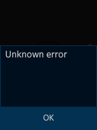
The error popup is defined according to the TAU library popup template. It contains an error message in the content area and an OK button in the footer:
<!--index.html-->
<div class="ui-page">
   <div id="error-popup" class="ui-popup">
      <div class="ui-popup-content" id="error-popup-message"></div>
      <div class="ui-popup-footer">
         <a id="error-ok-button" href="#" class="ui-btn ui-btn-footer-icon btn-icon-check" data-rel="back">OK</a>
      </div>
   </div>
</div>
The popup can be displayed at the application start if the magnetic sensor is not supported on the device, or when an error occurs after the magnetic sensor has started. The application closes automatically when the OK button is pressed.
Accessing Sensor Data
The Metal Detector application uses the magnetic sensor to indicate the value and direction of the measured magnetic field. Access to the data from the magnetic sensor is essential for proper application operation.
To access the sensor data:
- Initialize the application.
The following code snippet shows how the application gains access to the magnetic sensor data.
/* js/models/sensor.js */
var sensorService = null,
    sensor = null,
    SENSOR_TYPE = 'MAGNETIC';

function init()
{
   sensorService = tizen.sensorservice ||
   (window.webapis && window.webapis.sensorservice) || null;

   try
   {
      sensor = sensorService.getDefaultSensor(SENSOR_TYPE);
   }
   catch (error)
   {
      console.error('API is not supported!', error.message);
      e.fire('not.supported');

      return;
   }
   startSensor();
}
The application tries to access the sensor service. The sensorService interface provides methods to access the different types of sensors supported by device. If the sensor service is available, the application calls the getDefaultSensor() method with the MAGNETIC string as a parameter. In case of failure, the application fires the not.supported event and shows the error popup. If successful, the application gains access to the Sensor object from Sensor API and calls the startSensor() method on it to obtain the value that is currently returned by the magnetic sensor.
- Start the application.
The start() method from the Sensor API takes 2 parameters:
- The onSensorStartSuccess() success callback sets the isSensorStarted flag value to true and registers the magnetic sensor change listener. As a result, after each sensor value change, the onGetSuccess() method is called and the model.magnetic.update event is fired. This event delivers the current sensor data and is listened to by the main view module to update the UI.
- The onSensorStartError() error callback sets the isSensorStarted flag value to false and fires the model.magnetic.error event. This event is listened to by the main view module to display the error popup, if necessary.
/* js/models/magnetic.js */ var isSensorStarted = false; function onGetSuccess(sensorData) { e.fire('update', sensorData); } function onSensorStartSuccess() { isSensorStarted = true; sensor.setChangeListener(onGetSuccess); } function onSensorStartError(error) { isSensorStarted = false; e.fire('error', error); } function startSensor() { if (isSensorStarted) { return; } sensor.start(onSensorStartSuccess, onSensorStartError); } - Update the magnetic event information.
When the model.magnetic.update event occurs, the onMagneticUpdate() method from the main view module is called.
/* js/views/main.js */ function onMagneticUpdate(event) { var data = event.detail, x = data.x, y = data.y, z = data.z, value = calculations.count3dVectorLength(x, y, z); setPointerThickness(value); setPointerRotation(x, y); setValue(value); } - Obtain the vector values.
Obtain 3 vectors of the magnetic sensor value. The application uses the count3dVectorLength() method from the js/helpers/calculations.js module to calculate the result vector.
/* js/views/main.js */
function count3dVectorLength(x, y, z)
{
   return Math.sqrt(Math.pow(x, 2) + Math.pow(y, 2) + Math.pow(z, 2));
}
This method is based on the coordinates of the 3 given 3D vectors and calculates the vector with the result length. The calculated value is used by other methods to update the UI.
The setValue() method takes the value calculated by the count3dVectorLength() method and simply updates the div element with the info ID.
/* js/views/main.js */ var info = null; function setValue(value) { info.innerText = value.toFixed(0); } function init() { info = document.getElementById('info'); } - Calculate the result.
The setPointerRotation() method takes the coordinates of the 2 vectors (x and y) and uses the Math.atan2() method to calculate the angle in radians between the given point (x, y) and the positive OX axis. The calculated value is used to set the webkit-transform CSS attribute that allows you to rotate the div element with the pointer ID.
/* js/views/main.js */
var pointer = null;

function setPointerRotation(x, y)
{
   var rotation = -calculations.toDegrees(Math.atan2(y, x));

   pointer.style.webkitTransform = 'rotate(' + rotation + 'deg)';
}

function init()
{
   pointer = document.getElementById('pointer');
}
The setPointerThickness() method takes the value calculated by the count3dVectorLength() method and calculates the border width of the div element with the border ID.
/* js/views/main.js */
var border = null,
    LOWER_THRESHOLD = 30,
    UPPER_THRESHOLD = 300,
    MIN_POINTER_THICKNESS = 2;

function setPointerThickness(value)
{
   var minThickness = (pointer.offsetWidth - cover.offsetWidth) / 2 -  MIN_POINTER_THICKNESS,
       relativeStep = (UPPER_THRESHOLD - LOWER_THRESHOLD) / minThickness,
       pixelStep = 0;

   if (value < LOWER_THRESHOLD)
   {
      border.style.borderWidth = minThickness + 'px';
   }
   else if (value > UPPER_THRESHOLD)
   {
      border.style.borderWidth = 0;
   }
   else
   {
      pixelStep = minThickness - Math.floor((value - LOWER_THRESHOLD) / relativeStep);
      border.style.borderWidth = pixelStep + 'px';
   }
}

function init()
{
   border = document.getElementById('border');
}
This method is based on 3 constant values. The LOWER_THRESHOLD and UPPER_THRESHOLD constant values determine the working range for the border element:
When the given value is lower than the LOWER_THRESHOLD, the border width of the border element is the biggest to cover the maximum area of the pointer element (and make it almost invisible). The application uses the MIN_POINTER_THICKNESS constant value to ensure a minimum of the pointer element visibility.
When the given value is greater than the UPPER_THRESHOLD, the border width of the border element is equal to 0 to show the maximum area of the pointer element.
When the given value is between LOWER_THRESHOLD and UPPER_THRESHOLD, the application calculates the correct value of the border width expressed in pixels.