Device sensors
Tizen provides functions for managing sensors and receiving sensor data.
The main features of the Sensor API include:
-
Sensor listener
You can detect sensors and monitor their availability with the sensor listeners. The listeners receive registered sensor events and deliver the event data to applications at predefined intervals.
Sensor listeners can be added or removed at any time. The applications can add multiple sensor listeners for the same sensor type.
After you have created a sensor listener for a specific sensor and subscribed for sensor events, you can monitor the device’s internal sensors for sensor value changes. The application can receive the sensor data only when the data is modified. You can also request the device to record sensor data and query for previously recorded data.
When running an application on the emulator, you can use Emulator Control Panel to simulate sensor data for the application.
A working example for sensor listeners is provided.
-
Sensor handle
With the sensor handle, you can access the sensor hardware data:
- Sensor name
- Sensor vendor
- Sensor type
- Resolution
- Sensing interval
- Measurement range
-
Sensor types
A device can have various physical and virtual sensors. The following table lists the sensors supported by Tizen:
Note
Not all devices support all sensors, so each sensor is not necessarily available on all devices. You can check whether a sensor is supported. For more information, see System Information.
-
Sensor URI
A sensor URI is in the form
http://<vendor>/sensor/<category>/<sensor-type>/<sensor-name>. The/<sensor-name>element of the URI can be omitted:-
For platform-defined sensors, the vendor must be
tizen.org. -
The category can be either
generalorhealthinfo. Thehealthinfocategory means that an application must have thehttp://tizen.org/privilege/healthinfoprivilege to get the corresponding sensor handle. -
If the
/<sensor-name>element is omitted, the URI denotes any sensors of the given type and therefore can correspond to more than 1 sensor. Otherwise, each URI refers to a specific sensor in the device.For example, the
http://tizen.org/sensor/general/lightURI denotes all the light sensors in the device, whereashttp://tizen.org/sensor/general/light/frontonly refers to the light sensor namedfront.
-
Prerequisites
To use the functions and data types of the Sensor API, include the <sensor.h> header file in your application:
#include <sensor.h>
Create a sensor listener
If an application wants to observe data from a specific sensor, it must first check whether the sensor is supported. Then, you can create a sensor listener handle on the sensor:
-
To observe a specific sensor type, for example, accelerometer, check its availability:
bool supported = false; sensor_is_supported(SENSOR_ACCELEROMETER, &supported); if (!supported) { /* Accelerometer is not supported on the current device */ } -
For a specific supported sensor type, a device can have multiple sensors.
You can acquire all sensors or only the default sensor (designated by the device vendor) of a given type. The following example shows how to get the default accelerometer of the device:
sensor_h sensor; sensor_get_default_sensor(SENSOR_ACCELEROMETER, &sensor); -
After getting a sensor handle, you can create a listener handle upon the sensor handle:
sensor_listener_h listener;
sensor_create_listener(sensor, &listener);
Subscribe to sensor events
If a listener is created successfully, it is able to observe sensor data changes through the listener. In addition, you can set several parameters, including the update interval of the sensor data and the power-save behavior of the listener. The following example shows how to set the parameters and listen for changes in sensor data:
-
To listen for sensor events, define a callback function and register it to the listener:
/* Define callback */
void
example_sensor_callback(sensor_h sensor, sensor_event_s events[], int events_count, void *user_data)
{
    /*
       If a callback is used to listen for different sensor types,
       it can check the sensor type
    */
    sensor_type_e type;
    sensor_get_type(sensor, &type);
    int i = 0;
    if (type == SENSOR_ACCELEROMETER) {
       for (i = 0; i < events_count; i++) {
          unsigned long long timestamp = events[i].timestamp;
          int accuracy = events[i].accuracy;
          float x = events[i].values[0];
          float y = events[i].values[1];
          float z = events[i].values[2];
       }
    } else if (type == SENSOR_HRM_LED_GREEN) {
        unsigned long long timestamp = events[0].timestamp;
        int v = (int)events[0].values[0];
    }
}
/* Set interval */
sensor_listener_set_interval(listener, 100);

/* Register callback */
sensor_listener_set_events_cb(listener, example_sensor_callback, NULL);
In the above example, the update interval for the sensor data is set to 100 ms.
-
To listen for sensor events, start the listener:
sensor_listener_start(listener);The callback function starts to be called at least once per the given interval. You can start multiple listeners on the same sensor with different intervals. In this case, the shortest interval is chosen.
Some sensors are event-driven, meaning that they emit sensor events only if their data changes. For example, the proximity sensor emits its data only if the proximity value changes. For event-driven sensors, the update interval is ignored.
-
While the listener is running, you can change the listener settings:
-
You can change the listener update interval:
sensor_listener_set_interval(listener, 200);The above example changes the update interval of a given listener to 200 ms.
-
You can change the power-save behavior of the listener.
By default, the listener automatically stops listening for the sensor data, if the display is switched off or the device goes to the power-save mode. You can override such behavior:
sensor_listener_set_attribute_int(listener, SENSOR_ATTRIBUTE_PAUSE_POLICY, SENSOR_PAUSE_NONE);The above example makes the listener listen for the sensor data regardless of the display state and the power-save mode. However, it does not prevent the device from going to sleep mode. To listen for the sensor data, the device must be awake anyway.
-
-
When the sensor data is no more necessary, stop the listener:
sensor_listener_stop(listener); -
When a listener is no longer needed, release its resources explicitly:
sensor_destroy_listener(listener);
Request sensor data recording
Tizen supports long-term data recording for specific sensor types. For example, it can collect pedometer data for a month, by simply requesting the device to record pedometer data:
-
Not all sensor types can be recorded. Check whether a sensor is supported and allows recording on the current device before actually making the record request.
bool supported = false; sensor_recorder_is_supported(SENSOR_HUMAN_PEDOMETER, &supported); if (!supported) { /* Pedometer is not supported or cannot be recorded on the current device */ } -
You can set various recording options according to your needs.
For example, for the pedometer, its retention period can be designated. The following example shows how to create an option handle to record pedometer data for a month:
sensor_recorder_option_h option; sensor_recorder_create_option(&option); /* 720 hours (30 days) */ sensor_recorder_option_set_int(option, SENSOR_RECORDER_OPTION_RETENTION_PERIOD, 30 * 24); -
With the option handle, send the recording request for the pedometer data:
sensor_recorder_start(SENSOR_HUMAN_PEDOMETER, option);Even if the application terminates or the device reboots, the system automatically continues to record pedometer data. As the retention period is set to 720 hours in the above example, the data older than 720 hours is erased automatically. If multiple applications set different retention periods, the longest one is chosen.
-
When you no longer need to record pedometer data, stop the recording:
sensor_recorder_stop(SENSOR_HUMAN_PEDOMETER);However, if another application has requested for the same sensor data, remember that the recording is not stopped.
Query recorded sensor data
You can query the recorded sensor data with several query parameters. The query parameters vary between sensor types. For the pedometer, for example, you can get the daily step counts for the last 7 days by setting the necessary parameters:
-
Create a query.
In the following example, you get an aggregated data record per day (since
SENSOR_RECORDER_QUERY_TIME_INTERVALis set to 24 hours) and a day starts at 7 AM (not at midnight, sinceSENSOR_RECORDER_QUERY_ANCHOR_TIMEis set to 7 AM):sensor_recorder_query_h query; sensor_recorder_create_query(&query); /* Start 7 days ago */ sensor_recorder_query_set_time(query, SENSOR_RECORDER_QUERY_START_TIME, (time_t)(time(NULL) - (7 * 24 * 3600))); /* End now */ sensor_recorder_query_set_time(query, SENSOR_RECORDER_QUERY_END_TIME, time(NULL)); /* Aggregate every 24 hours */ sensor_recorder_query_set_int(query, SENSOR_RECORDER_QUERY_TIME_INTERVAL, 24 * 60); /* Start the aggregation at 7 AM */ sensor_recorder_query_set_time(query, SENSOR_RECORDER_QUERY_ANCHOR_TIME, (time_t)(7 * 3600)); -
With the query handle, retrieve the actual aggregated data:
sensor_recorder_read(SENSOR_HUMAN_PEDOMETER, query, example_sensor_recorder_callback, NULL);The
sensor_recorder_read()function is asynchronous. The synchronous variant issensor_recorder_read_sync(). -
Inside the
example_sensor_recorder_callback()callback, each record attribute can be extracted:void example_sensor_recorder_callback(sensor_type_e type, sensor_recorder_data_h data, int remains, sensor_error_e error, void *user_data) { int step; double distance; time_t start; time_t end; if (error != SENSOR_ERROR_NONE) return; sensor_recorder_get_time(data, &start, &end); sensor_recorder_get_int(data, SENSOR_RECORDER_DATA_STEPS, &step); sensor_recorder_get_double(data, SENSOR_RECORDER_DATA_DISTANCE, &distance); }
Working example for sensor listeners
This example demonstrates how to create a sensor listener for the accelerometer and listen for sensor events.
#include <stdio.h>
#include <stdbool.h>
#include <errno.h>

#include <glib.h> /* use GMainLoop to run sensor listener */

#include <sensor.h>

/* Check if sensor exists and create sensor listener */
static int create_sensor_listener(sensor_type_e sensor_type, sensor_listener_h *sensor_listener)
{
    int ret = 0;
    bool supported = false;
    sensor_h sensor = NULL;
    sensor_listener_h listener = NULL;

    if (!sensor_listener) {
        printf("Invalid parameter: sensor_listener is NULL\n");
        return -EINVAL;
    }

    ret = sensor_is_supported(sensor_type, &supported);
    if (ret != SENSOR_ERROR_NONE) {
        printf("Failed to call sensor_is_supported: ret(%d)\n", ret);
        return ret;
    }
    if (!supported) {
        printf("Accelerometer is not supported on the current device\n");
        return -EINVAL;
    }

    ret = sensor_get_default_sensor(sensor_type, &sensor);
    if (ret != SENSOR_ERROR_NONE) {
        printf("Failed to call sensor_get_default_sensor: ret(%d)\n", ret);
        return ret;
    }
    if (!sensor) {
        printf("Failed to get sensor\n");
        return -EINVAL;
    }

    ret = sensor_create_listener(sensor, &listener);
    if (ret != SENSOR_ERROR_NONE) {
        printf("Failed to call sensor_create_listener: ret(%d)\n", ret);
        return ret;
    }
    if (!listener) {
        printf("Failed to create listener\n");
        return -EINVAL;
    }

    *sensor_listener = listener;
    return 0;
}

/* An callback function when accelerometer event is occured */
static void accelerometer_callback(sensor_h sensor, sensor_event_s events[], int events_count, void *user_data)
{
    int ret = 0;
    sensor_type_e type;

    ret = sensor_get_type(sensor, &type);
    if (ret != SENSOR_ERROR_NONE) {
        printf("Failed to get sensor type: ret(%d)\n", ret);
        return;
    }
    if (type != SENSOR_ACCELEROMETER) {
        printf("Invalid sensor type: expected accelerometer(%d) but %d was given\n",
                SENSOR_ACCELEROMETER, type);
        return;
    }

    for (int i = 0; i < events_count; ++i) {
        printf("Accelerometer: [ ");
        for (int j = 0; j < events[i].value_count; ++j)
            printf("%f, ", events[i].values[j]);
        printf("time: %llu(us) ]\n", events[i].timestamp);
    }
}

int main(int argc, char **argv)
{
    int ret = 0;
    sensor_listener_h listener = NULL;
    GMainLoop *mainloop = NULL;

    ret = create_sensor_listener(SENSOR_ACCELEROMETER, &listener);
    if (ret != 0) {
        printf("Failed to create sensor listener: ret(%d)\n", ret);
        return EINVAL;
    }

    /* Set the sensor reading interval as 100ms */
    ret = sensor_listener_set_interval(listener, 100);
    if (ret != SENSOR_ERROR_NONE) {
        printf("Failed to set interval: ret(%d)\n", ret);
        sensor_destroy_listener(listener);
        return EINVAL;
    }

    /* Set listener callback */
    ret = sensor_listener_set_events_cb(listener, accelerometer_callback, NULL);
    if (ret != SENSOR_ERROR_NONE) {
        printf("Failed to set event callback: ret(%d)\n", ret);
        sensor_destroy_listener(listener);
        return EINVAL;
    }

    /* Start to listen the sensor */
    ret = sensor_listener_start(listener);
    if (ret != SENSOR_ERROR_NONE) {
        printf("Failed to start sensor listener: ret(%d)\n", ret);
        sensor_destroy_listener(listener);
        return EINVAL;
    }

    mainloop = g_main_loop_new(NULL, FALSE);
    g_main_loop_run(loop);

    /* The listener should be destroied after use */
    sensor_destroy_listener(listener);

    return 0;
}
Accelerometer
The accelerometer measures changes in the velocity of a device. It is a combination of gravity and linear acceleration components. The accelerometer measures the device’s accelerometer vector in 3 axes relative to its body frame.
An acceleration of 1g always exists on the axis aligned to Earth’s gravity. If the device is at rest, the sensor data reads 1g (the gravity offset) on one of the device axes and tells you which device axis is aligned to the direction of gravity. A falling device that has reached terminal velocity ideally shows the accelerometer value of 0 on all axes. The change in the effect of Earth’s gravity is observed on the 3 device axes by rotating the device along any of the 3 axes.
The linear acceleration components which correspond to the measure of the linear motion subjected on the device can be obtained by removing the gravity components from the accelerometer data.
The accelerometer provides 3 components of acceleration (X, Y, and Z), as the following figure illustrates.
Figure: Accelerometer vector and axes
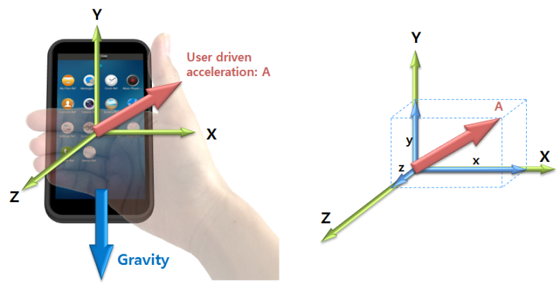
The accelerometer outputs 4 values: 3 Cartesian axis values and a timestamp. The accelerometer sensor measures and returns the axes’ values in “m/s2” (meters per second squared). When a device is moved in the ±X, ±Y, or ±Z direction, the corresponding output increases (+) or decreases (-).
The following table lists the measurement data that the accelerometer provides:
Table: Measurement data detected by the accelerometer
| Measurement | Type | Range | Unit |
|---|---|---|---|
| Timestamp | unsigned long long |
- | Microseconds |
| values[0]: X | float |
Min. value = -19.6 Max. value = 19.6 |
m/s2 |
| values[1]: Y | float |
Min. value = -19.6 Max. value = 19.6 |
m/s2 |
| values[2]: Z | float |
Min. value = -19.6 Max. value = 19.6 |
m/s2 |
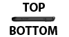
The following table provides information about the accelerometer output for a device at rest.
Table: Accelerometer output for a device at rest
| Position | 1 | 2 | 3 | 4 | 5 | 6 |
|---|---|---|---|---|---|---|
| Diagram |  |
 |
 |
 |
 |
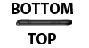 |
| values[0]: X | 0g | 1g | 0g | -1g | 0g | 0g |
| values[1]: Y | 1g | 0g | -1g | 0g | 0g | 0g |
| values[2]: Z | 0g | 0g | 0g | 0g | 1g | -1g |
| Axis up (down) | Y | X | -Y | -X | Z | -Z |
| X-polarity | 0 | + | 0 | - | 0 | 0 |
| Y-polarity | + | 0 | - | 0 | 0 | 0 |
| Z-polarity | 0 | 0 | 0 | 0 | + | - |
Geomagnetic orientation sensor
The geomagnetic orientation sensor combines the 3-axis accelerometer and 3-axis magnetic sensor to determine the orientation (rotation angles) of the device. The geomagnetic orientation sensor is similar to the orientation sensor but does not use a gyroscope. The geomagnetic orientation is the output of a software/hardware-based sensor fusion solution that uses the accelerometer and magnetic sensor. The geomagnetic orientation sensor output is an alternative representation to the geomagnetic rotation vector sensor output used to determine the rotation of the device, and it is calculated in terms of Euler angles:
- Azimuth
- Pitch
- Roll
The following table lists the measurement data that the geomagnetic orientation sensor provides:
Table: Measurement data detected by the geomagnetic orientation sensor
| Measurement | Type | Range | Unit |
|---|---|---|---|
| Timestamp | unsigned long long |
- | Microseconds |
| values[0]: Azimuth | float |
Min. value = 0 Max. value = 360 |
Degrees (°) |
| values[1]: Pitch | float |
Min. value = -180 Max. value = 180 |
Degrees (°) |
| values[2]: Roll | float |
Min. value = -90 Max. value = 90 |
Degrees (°) |
Geomagnetic rotation vector sensor
The geomagnetic rotation vector sensor is the output of a software/hardware-based sensor fusion solution that uses the accelerometer and magnetic sensors to compute the orientation of the device. In this sensor, the computed orientation is free of any drift, but it is inaccurate compared to a sensor fusion solution using the gyroscope sensor. The geomagnetic rotation vector sensor represents the orientation of the device as a combination of an angle and an axis on which the device has rotated through a specific angle around an axis (X, Y, or Z).
The following table lists the measurement data that the geomagnetic rotation vector sensor provides:
Table: Measurement data detected by the geomagnetic rotation vector sensor
| Measurement | Type | Range | Unit |
|---|---|---|---|
| Timestamp | unsigned long long |
- | Microseconds |
| Accuracy | sensor_data_accuracy_e |
- | int |
| values[0]: X | float |
Min. value = -1 Max. value = 1 |
- |
| values[1]: Y | float |
Min. value = -1 Max. value = 1 |
- |
| values[2]: Z | float |
Min. value = -1 Max. value = 1 |
- |
| values[3]: W | float |
Min. value = -1 Max. value = 1 |
- |
Gravity sensor
The gravity sensor is a virtual sensor derived from the 3-axis acceleration sensor. The 3-axis gravity components provide a measure of the effect of Earth’s gravity observed on the device reference axes. The gravity components measured on a device vary based on changes in the device orientation, and hence they provide a measure of the rotation to which the device is subjected.
Figure: Gravity sensor vector and axes
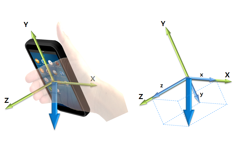
The gravity sensor outputs 4 values: 3 Cartesian axis values and a timestamp. The gravity sensor measures and returns axes values in “m/s2” (meters per second squared). When a device is rotated in the ±X, ±Y, or ±Z direction, the corresponding output increases (+) or decreases (-).
The following table lists the measurement data that the gravity sensor provides:
Table: Measurement data detected by the gravity sensor
| Measurement | Type | Range | Unit |
|---|---|---|---|
| Timestamp | unsigned long long |
- | Microseconds |
| values[0]: X | float |
Min. value = -9.8 Max. value = 9.8 |
m/s2 |
| values[1]: Y | float |
Min. value = -9.8 Max. value = 9.8 |
m/s2 |
| values[2]: Z | float |
Min. value = -9.8 Max. value = 9.8 |
m/s2 |
Gyroscope
The gyroscope detects angular velocity or angular rates of a device. The 3D gyroscope data is considered to be very sensitive in detecting incremental rotation angles. The rotation angles obtained by integrating the angular rates over a longer duration are inaccurate due to the build-up of drift.
Figure: Gyroscope vector and axes
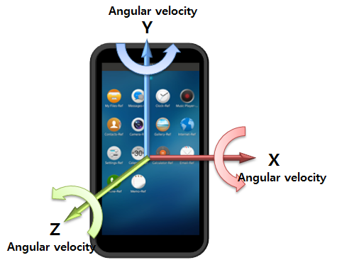
The following table lists the measurement data that the gyroscope provides:
Table: Measurement data detected by the gyroscope
| Measurement | Type | Range | Unit |
|---|---|---|---|
| Timestamp | unsigned long long |
- | Microseconds |
| values[0]: X | float |
Min. value = -573.0 Max. value = 573.0 |
Degrees/s (°/s) |
| values[1]: Y | float |
Min. value = -573.0 Max. value = 573.0 |
Degrees/s (°/s) |
| values[2]: Z | float |
Min. value = -573.0 Max. value = 573.0 |
Degrees/s (°/s) |
Gyroscope orientation sensor
The gyroscope orientation sensor combines the 3-axis accelerometer and 3-axis gyroscope to determine the orientation (rotation angles) of the device. The gyroscope orientation sensor is similar to the orientation sensor, but it does not use a geomagnetic field. Thus, yaw represents a relative rotation angle, not an absolute reference. The gyroscope orientation is the output of a software/hardware-based sensor fusion solution that uses the accelerometer and gyroscope. The gyroscope orientation sensor output is an alternative representation to the gyroscope rotation vector sensor output used to determine the rotation of the device, and it is calculated in terms of Euler angles:
- Yaw
- Pitch
- Roll
The following table lists the measurement data that the gyroscope orientation sensor provides:
Table: Measurement data detected by the gyroscope orientation sensor
| Measurement | Type | Range | Unit |
|---|---|---|---|
| Timestamp | unsigned long long |
- | Microseconds |
| values[0]: Yaw | float |
Min. value = 0 Max. value = 360 |
Degrees (°) |
| values[1]: Pitch | float |
Min. value = -180 Max. value = 180 |
Degrees (°) |
| values[2]: Roll | float |
Min. value = -90 Max. value = 90 |
Degrees (°) |
Gyroscope rotation vector sensor
The gyroscope rotation vector sensor is the output of a software/hardware-based sensor fusion solution that uses the accelerometer and gyroscope to compute the orientation of the device. In this sensor, the pitch and roll equivalent representations are free of drift while the yaw equivalent component is allowed to drift due to the absence of the magnetic sensor. The gyroscope rotation vector sensor represents the orientation of the device as a combination of an angle and an axis on which the device has rotated through a specific angle around an axis (X, Y, or Z).
The following table lists the measurement data that the gyroscope rotation vector sensor provides:
Table: Measurement data detected by the gyroscope rotation vector sensor
| Measurement | Type | Range | Unit |
|---|---|---|---|
| Timestamp | unsigned long long |
- | Microseconds |
| Accuracy | sensor_data_accuracy_e |
- | int |
| values[0]: X | float |
Min. value = -1 Max. value = 1 |
- |
| values[1]: Y | float |
Min. value = -1 Max. value = 1 |
- |
| values[2]: Z | float |
Min. value = -1 Max. value = 1 |
- |
| values[3]: W | float |
Min. value = -1 Max. value = 1 |
- |
Heart rate monitor LED green sensor
The heart rate monitor (HRM) LED green sensor measures the amount of green light that is reflected back from a person’s blood vessel.
The following table lists the measurement data that the HRM LED green sensor provides:
Table: Measurement data detected by the HRM LED green sensor
| Measurement | Type | Range | Unit |
|---|---|---|---|
| Timestamp | unsigned long long |
- | Microseconds |
| values[0]: HRM green light value | int |
Min. value = 0 Max. value = 4194304 |
- |
Heart rate monitor LED green batch Sensor
The heart rate monitor (HRM) LED green batch sensor measures the amount of green light that is reflected back from a person’s blood vessel. The sensor buffers and sends the recorded data in batches. The sensor must be power-efficient and support batch processing.
The following table lists the measurement data that the HRM LED green batch sensor provides:
Table: Measurement data detected by the HRM LED green batch sensor
| Measurement | Type | Range | Unit |
|---|---|---|---|
| Timestamp | unsigned long long |
- | Microseconds |
| values[0]: HRM green light value | int |
Min. value = 0 Max. value = 4194304 |
- |
| values[1]: X | int |
Min. value = -4096 Max. value = 4096 |
- |
| values[2]: Y | int |
Min. value = -4096 Max. value = 4096 |
- |
| values[3]: Z | int |
Min. value = -4096 Max. value = 4096 |
- |
| values[4]: Index | int |
Sequential index of sensor event | - |
Heart rate monitor LED IR sensor
The heart rate monitor (HRM) LED infrared (IR) sensor measures the amount of infrared light that is reflected back from a person’s blood vessel.
The following table lists the measurement data that the HRM LED IR sensor provides:
Table: Measurement data detected by the HRM LED IR sensor
| Measurement | Type | Range | Unit |
|---|---|---|---|
| Timestamp | unsigned long long |
- | Microseconds |
| values[0]: HRM IR light value | int |
Min. value = 0 Max. value = 4194304 |
- |
Heart rate monitor LED red sensor
The heart rate monitor (HRM) LED red sensor measures the amount of red light that is reflected back from a person’s blood vessel.
The following table lists the measurement data that the HRM LED red sensor provides:
Table: Measurement data detected by the HRM LED red sensor
| Measurement | Type | Range | Unit |
|---|---|---|---|
| Timestamp | unsigned long long |
- | Microseconds |
| values[0]: HRM red light value | int |
Min. value = 0 Max. value = 4194304 |
- |
Heart rate monitor sensor
The heart rate monitor (HRM) sensor measures a person’s heart rate in real time.
The following table lists the measurement data that the HRM sensor provides:
Table: Measurement data detected by the HRM sensor
| Measurement | Type | Range | Unit |
|---|---|---|---|
| Timestamp | unsigned long long |
- | Microseconds |
| values[0]: Beats per minute | int |
Min. value = 0 Max. value = 240 |
- |
Heart rate monitor batch sensor
The heart rate monitor (HRM) batch sensor measures a person’s heart rate. The sensor buffers and sends the recorded data in batches. The sensor must be power-efficient and support batch processing.
The following table lists the measurement data that the HRM batch sensor provides:
Table: Measurement data detected by the HRM batch sensor
| Measurement | Type | Range | Unit |
|---|---|---|---|
| Timestamp | unsigned long long |
- | Microseconds |
| values[0]: State | sensor_hrm_batch_state_e |
- | - |
| values[1]: Beats per minute | int |
Min. value = 0 Max. value = 240 |
- |
| values[2]: R wave-to-R wave interval | int |
- | Millisecond |
Humidity sensor
The humidity sensor measures the relative ambient air humidity in percentage.
The following table lists the measurement data that the humidity sensor provides:
Table: Measurement data detected by the humidity sensor
| Measurement | Type | Range | Unit |
|---|---|---|---|
| Timestamp | unsigned long long |
- | Microseconds |
| values[0]: humidity | float |
100 | % |
Light sensor
The light sensor detects the brightness of ambient light. It can be used to measure the brightness level.
As an example use case, the light sensor can be used to control the brightness of the screen. In a dark environment, the light sensor detects the brightness of the environment and can be used to increase the device screen backlight brightness level. In a brighter environment, the backlight brightness level is lowered to save battery power.
The following table lists the measurement data that the light sensor provides:
Table: Measurement data detected by the light sensor
| Measurement | Type | Range | Unit |
|---|---|---|---|
| Timestamp | unsigned long long |
- | Microseconds |
| values[0]: Level | float |
Min. value = 0 Max. value = 45875 |
Lux |
Linear acceleration sensor
The linear acceleration sensor is derived from the accelerometer by excluding the gravity value, and it measures the user-driven changes in the velocity. The linear acceleration sensor is used to detect the dynamic movement of the device and analyze the user’s motion profile. The 3-axis linear acceleration components provide a measure of the combined linear motion subjected to the device in Euclidean space.
The linear acceleration sensor provides 3 components of acceleration (X, Y, and Z), as the following figure illustrates.
Figure: User-acceleration sensor vector and axes
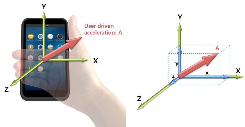
The linear acceleration sensor outputs 4 values: 3 Cartesian axis values and a timestamp. The linear acceleration sensor measures and returns axes values in “m/s2” (meters per second squared). When a device is accelerated in the ±X, ±Y, or ±Z direction, the corresponding output increases (+) or decreases (-). The acceleration output is shown in the same direction as the user-driven force.
The following table lists the measurement data that the linear acceleration sensor provides:
Table: Measurement data detected by the linear acceleration sensor
| Measurement | Type | Range | Unit |
|---|---|---|---|
| Timestamp | unsigned long long |
- | Microseconds |
| values[0]: X | float |
Min. value = -19.6 Max. value = 19.6 |
m/s2 |
| values[1]: Y | float |
Min. value = -19.6 Max. value = 19.6 |
m/s2 |
| values[2]: Z | float |
Min. value = -19.6 Max. value = 19.6 |
m/s2 |
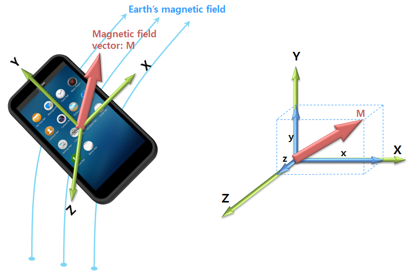
Magnetic sensor
The magnetic sensor is a 3-axis electronic compass (sometimes referred to as a “magnetometer” or “geomagnetic sensor”). It can also be used in determining the azimuth component of the device orientation provided that the tilt of the device is already computed. The magnetic sensor measures the Earth’s magnetic field strength and fluctuations and splits the measurement into X, Y, and Z components.
The following factors can have an impact on the sensor readings:
- The weather or the season of the year
- Your location on the planet
- Nearby, strong magnetic fields, such as magnets, electric coils, or objects which contain a ferrite element
The following table lists the measurement data that the magnetic sensor provides:
Table: Measurement data detected by the magnetic sensor
| Measurement | Type | Unit |
|---|---|---|
| Timestamp | unsigned long long |
Microseconds |
| values[0]: X | float |
µT (microteslas) |
| values[1]: Y | float |
µT (microteslas) |
| values[2]: Z | float |
µT (microteslas) |
The magnetic sensor uses the 3-axis Cartesian space coordinate system, as the following figure illustrates.
Figure: Magnetic field vector and axes
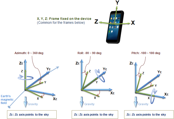
Orientation sensor
The orientation sensor combines the 3-axis accelerometer, 3-axis magnetic sensor, and 3-axis gyroscope to determine the orientation (rotation angles) of the device. The orientation is the output of a software/hardware-based sensor fusion solution that uses the accelerometer, magnetic sensor, and gyroscope. The orientation sensor output is an alternative representation to the rotation vector sensor output used to determine the rotation of the device, and it is calculated in terms of Euler angles:
- Azimuth
- Pitch
- Roll
The following table lists the measurement data that the orientation sensor provides:
Table: Measurement data detected by the orientation sensor
| Measurement | Type | Range | Unit |
|---|---|---|---|
| Timestamp | unsigned long long |
- | Microseconds |
| values[0]: Azimuth | float |
Min. value = 0 Max. value = 360 |
Degrees (°) |
| values[1]: Pitch | float |
Min. value = -180 Max. value = 180 |
Degrees (°) |
| values[2]: Roll | float |
Min. value = -90 Max. value = 90 |
Degrees (°) |
The angular positions are measured using a fixed frame reference (XE, YE, ZE).
Figure: Angular positions and the fixed frame reference
Pedometer
The pedometer detects the user’s steps, and returns the number of steps taken by the user since the last reboot, while at least 1 application is using the pedometer. The timestamp of the event denotes the time when the last step was taken. In addition to the number of steps, it also returns other tracking data to further describe the user’s activity status. For example, it provides the user’s moving distance and burned calories. All the values are reset to zero when the system reboots.
Normally, a callback function is invoked whenever a new step is detected. However, to be power-efficient, the sensor can internally accumulate its detected events while the system sleeps. In this case, the accumulated data is reported when the system wakes up, that is, the display is switched on. In addition, even though the display is not switched on explicitly, the sensor can wake up the device to deliver its accumulated data occasionally.
If you want to track the user’s steps continuously, do not stop the sensor listener to be sure that it keeps running. If there is no application listening to the sensor, it stops counting the steps.
The following table lists the measurement data that the pedometer provides:
Table: Measurement data detected by the pedometer
| Measurement | Type | Range | Unit |
|---|---|---|---|
| Timestamp | unsigned long long |
- | Microseconds |
| values[0]: number of steps | int |
Min. value = 0 Max. value = 224 |
Steps |
| values[1]: number of walking steps | int |
Min. value = 0 Max. value = 224 |
Steps |
| values[2]: number of running steps | int |
Min. value = 0 Max. value = 224 |
Steps |
| values[3]: moving distance | float |
Min. value = 0 | Meters |
| values[4]: calories burned | float |
Min. value = 0 | kcal |
| values[5]: last speed | float |
Min. value = 0 | km/h |
| values[6]: last stepping frequency | float |
Min. value = 0 | Steps/second |
| values[7]: last pedestrian state | sensor_pedometer_state_e |
- | - |
The pedestrian state is SENSOR_PEDOMETER_STATE_UNKNOWN, SENSOR_PEDOMETER_STATE_STOP, SENSOR_PEDOMETER_STATE_WALK, or SENSOR_PEDOMETER_STATE_RUN.
Pressure sensor
The pressure sensor measures the atmospheric pressure in the device’s surrounding environment.
The following table lists the measurement data that the pressure sensor provides:
Table: Measurement data detected by the pressure sensor
| Measurement | Type | Range | Unit |
|---|---|---|---|
| Timestamp | unsigned long long |
- | Microseconds |
| values[0]: pressure | float |
Min. value = 260 Max. value = 1260 |
hPa (hectopascals) |
Proximity sensor
The proximity sensor detects the presence of nearby objects in close proximity to the sensor. It can be used to measure the distance between nearby objects and the device.
As an example use case, the proximity sensor can be used to lock or unlock the device screen. When the device user holds the device to their ear, the proximity sensor detects the user as an object and automatically locks the device screen. When the user moves the device away from their ear to input data, the proximity sensor determines that there are no nearby objects, and unlocks the screen.
The following table lists the measurement data that the proximity sensor provides:
Table: Measurement data detected by the proximity sensor
| Measurement | Type | Range | Unit |
|---|---|---|---|
| Timestamp | unsigned long long |
- | Microseconds |
| values[0]: proximity | float |
- | - |
Rotation vector sensor
The rotation vector sensor represents the orientation of the device as a combination of an angle and an axis, in which the device has rotated through a specific angle around an axis (X, Y, or Z). The rotation vector is the output of a software/hardware-based sensor fusion solution, which uses the accelerometer, gyroscope, and magnetic sensor as inputs to compute the orientation of the device.
The following table lists the measurement data that the rotation vector sensor provides:
Table: Measurement data detected by the rotation vector
| Measurement | Type | Range | Unit |
|---|---|---|---|
| Timestamp | unsigned long long |
- | Microseconds |
| Accuracy | sensor_data_accuracy_e |
- | int |
| values[0]: X | float |
Min. value = -1 Max. value = 1 |
- |
| values[1]: Y | float |
Min. value = -1 Max. value = 1 |
- |
| values[2]: Z | float |
Min. value = -1 Max. value = 1 |
- |
| values[3]: W | float |
Min. value = -1 Max. value = 1 |
- |
Significant motion sensor
The significant motion sensor detects when there is significant movement causing changes in the user location, for example, when the user is walking, biking, or in a moving vehicle.
The following table lists the measurement data that the significant motion sensor provides:
Table: Measurement data detected by the significant motion sensor
| Measurement | Type | Range | Unit |
|---|---|---|---|
| Timestamp | unsigned long long |
- | Microseconds |
| values[0]: significant motion detected | float |
- | - |
Sleep monitor
The sleep monitor tracks the user’s sleep quality. Once per minute, it reports whether the user sleeps. As this sensor usually needs to track the sleep quality over several hours, it must be power-efficient and work in a batch manner. While the system sleeps, or the display is off, the sensor keeps its detected data internally. When the sensor is unable to keep more data (its internal buffer is full), it wakes up the system and flushes all collected data. When flushing, the callback function is invoked repeatedly. The timestamp of each event can be used to figure out when the user was sleeping.
The following table lists the measurement data that the sleep monitor provides:
Table: Measurement data detected by the sleep monitor
| Measurement | Type | Unit |
|---|---|---|
| Timestamp | unsigned long long |
Microseconds |
| values[0]: user’s sleep state | sensor_sleep_state_e |
- |
The sleep state is SENSOR_SLEEP_STATE_UNKNOWN, SENSOR_SLEEP_STATE_WAKE, or SENSOR_SLEEP_STATE_SLEEP.
Depending on the device you are using, the available raw sensors are different and the sleep detection algorithm can also vary. In addition to the sleep state field, some specific device models can provide further data, as defined by the model manufacturer.
Temperature sensor
The temperature sensor measures the ambient room temperature in the device’s surrounding environment.
The following table lists the measurement data that the temperature sensor provides:
Table: Measurement data detected by the temperature sensor
| Measurement | Type | Range | Unit |
|---|---|---|---|
| Timestamp | unsigned long long |
- | Microseconds |
| values[0]: temperature | float |
Min. value = -30 Max. value = 100 |
°C |
Ultraviolet sensor
The ultraviolet (UV) sensor measures the ultraviolet index. The sensor detects and provides a measure of the UV rays the device is exposed to.
The following table lists the measurement data that the ultraviolet sensor provides:
Table: Measurement data detected by the ultraviolet sensor
| Measurement | Type | Range | Unit |
|---|---|---|---|
| Timestamp | unsigned long long |
- | Microseconds |
| values[0]: UV index | float |
Min. value = 0 Max. value = 15 |
UV index |
Uncalibrated gyroscope
The uncalibrated gyroscope detects angular velocity or angular rates of a device. The 3D uncalibrated gyroscope sensor is considered to be very sensitive in detecting incremental rotation angles. The rotation angles obtained by integrating the angular rates over a longer duration are inaccurate due to the build-up of drift. The uncalibrated gyroscope data also consists of drift compensation values for each axis, which can be used to subtract the drift from the detected angular rates. The values of drift for the 3 axes are obtained from the output of a software/hardware-based sensor fusion solution.
The following table lists the measurement data that the uncalibrated gyroscope provides:
Table: Measurement data detected by the uncalibrated gyroscope
| Measurement | Type | Range | Unit |
|---|---|---|---|
| Timestamp | unsigned long long |
- | Microseconds |
| values[0]: X | float |
Min. value = -573.0 Max. value = 573.0 |
Degrees/s (°/s) |
| values[1]: Y | float |
Min. value = -573.0 Max. value = 573.0 |
Degrees/s (°/s) |
| values[2]: Z | float |
Min. value = -573.0 Max. value = 573.0 |
Degrees/s (°/s) |
| values[3]: Drift around the X axis | float |
Min. value = -573.0 Max. value = 573.0 |
Degrees/s (°/s) |
| values[4]: Drift around the Y axis | float |
Min. value = -573.0 Max. value = 573.0 |
Degrees/s (°/s) |
| values[5]: Drift around the Z axis | float |
Min. value = -573.0 Max. value = 573.0 |
Degrees/s (°/s) |
Uncalibrated magnetic sensor
The uncalibrated magnetic sensor is a 3-axis electronic compass (sometimes referred to as a “magnetometer” or “geomagnetic sensor”). It can also be used in determining the azimuth component of the device orientation provided that the tilt of the device is already computed. It measures the Earth’s magnetic field strength and fluctuations, and splits the measurement into X, Y, and Z components. The uncalibrated magnetic sensor is similar in functionality to a magnetic sensor but does not perform hard iron calibration. Factory calibration and temperature compensation are applied.
The following factors can have an impact on the sensor readings:
- The weather or the season of the year
- Your location on the planet
- Nearby, strong magnetic fields, such as magnets, electric coils, or objects which contain a ferrite element
The following table lists the measurement data that the uncalibrated magnetic sensor provides:
Table: Measurement data detected by the uncalibrated magnetic sensor
| Measurement | Type | Unit |
|---|---|---|
| Timestamp | unsigned long long |
Microseconds |
| values[0]: X | float |
µT (microteslas) |
| values[1]: Y | float |
µT (microteslas) |
| values[2]: Z | float |
µT (microteslas) |
| values[3]: X-axis bias | float |
µT (microteslas) |
| values[4]: Y-axis bias | float |
µT (microteslas) |
| values[5]: Z-axis bias | float |
µT (microteslas) |
Related information
- Dependencies
- Since Tizen 2.4